A Makerslide based delta 3D printer
Posted by Jim Morris on 2012-12-16 16:47:33 +0000
UPDATE the project is currently hosted on Github
So I have been totally obsessed with 3D printing recently. After building a 3D printer from the Zentoolworks CNC framework (I actually got a 7x7 3D which they no longer sell), I decided to build a Delta 3D printer based on the Rostock and Kossel ideas.
My Zentoolworks works great, but is very slow and is limited to about a 7"x7"X5" build area. The prints are great though if printed at around 25mm/sec maximum. I used a 0.3mm JHead and Trinity Labs microextruder. Standard RAMPS/Arduino with Marlin firmware, and I use SFACT and Slic3r to slice, and Pronterface for the front end. It also doubles as a light duty mill, which I have used to mill PCBs and some plastic and MDF.
The Delta printers look great though and are a fascinating machine to watch print. They are also capable of relatively fast printing and very tall prints.
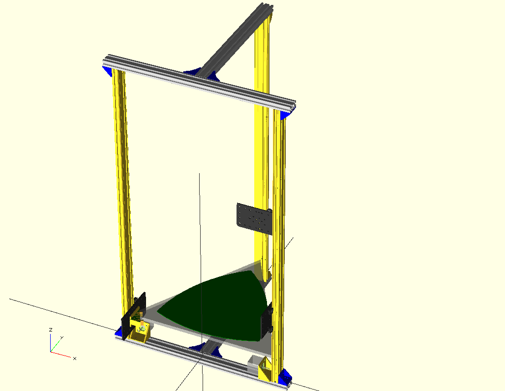
I decided I would shoot for a 12"x12"x12" build volume (or fairly close to that).
I took some basic design ideas from the Kossel, and a derivative called an Ostoc to simplify the frame. Most Deltas are based on an equilateral triangle design with 60 degree angles. As I wanted to build with off-the-shelf Misumi extrusions and brackets, I needed to keep everything orthogonal, ie right angles. The Ostoc accomplishes that.
I am experimenting with different drive mechanisms for the Makerslide carriages. I have implemented the standard Kossel fishing line drive, and this works well with no load, and it is fast, using the 18mm spool and Nema17s I have had the carriage moving up and down at 500mm/sec.
I have also implemented a leadscrew drive using McMaster 8 start 1" lead screws with some antibacklash nuts I printed. This is inherently a slower system as it only travels 1" (25.4mm) per revolution as opposed to the fishingline spool which can travel about 56mm per revolution (~2.2"). So I would expect at least half the speed, however with the anti backlash nut installed I was only able to get a top speed of 150mm/sec before the stepper stalled. It may be the anti backlash spring is too tight, so I need to rerun the tests without the spring loaded.
On my TODO list is to try #25 roller chain as the drive. This has the same speed potential as the fishingline drive as the drive Sprocket is 9 teeth and the chain is 1/4" pitch which gives about 57mm/rev. The downside is that most CNC roller chain implementations fix the chain at each end, and have the roller chain go through an S wrap around the drive sprocket, and the Stepper motor is on the carriage and pulls itself up and down the chain. This will add significant weight to the carriage, and will impact the maximum acceleration as well as speed due to inertia. The other methods of chain drive are considered not sutable for vertical applications, according to the many articles I read.
Calculating speed and distance
The calculations for distance travelled per revolution and maximum speed are pretty simple, here is a summary...
After a lot of experimentation, it seems that most stepper motors absolute maximum speed (at any micro step setting) is 10 revolutions/sec. That seems to be the top before all torque is lost. The more friction or weight in the system the lower that goes.
For a standard Nema17 set at 16 micro steps that is 3,200 steps per revolution.
Presuming an Arduino class MCU can step at around 30kHz or more, that would be 9.375 revolutions per second at 16 microsteps, which is pretty close to the maximum a stepper can do anyway.
Speed depends on how many mm can be moved per revolution. For most setups this seems to be between 25 and 50mm per revolution, so the maximum speed tends to be between 250mm/sec and 500mm/sec for the two extremes. (mm per rev * 10revs/sec).
The mm per revolution can be calculated for timing belts and roller chain by multiplying the pitch of the belt/chain by the number of teeth on the drive pulley. So for GT2 belts that is 2mm * 20 teeth (if you had a 20 tooth drive pulley) which is 40mm per revolution so maximum theoretical speed is 400mm/sec.
For a fishing line pulley the calculation is a little more complex...
mm per rotation= 2 x PI x (radiusOfPulley+radiusOfFilament)
So for the Kossel an 18mm diameter pulley with 0.5mm diameter line the result would be about 58mm per rotation, giving a top theoretical speed of 580mm/sec.
BOM and cost
The total cost of extrusions for the basic Ostoc-like frame is relatively cheap, the extrusions tend to run very cheap, but the brackets and nuts are the expensive items. (Openbeam uses standard 3mm nuts and bolts so is much cheaper, but at 15mm square is not sturdy enough for a large frame IMHO). Note the Kossel uses Openbeam. I use 2040 Misumi Extrusions.
The price breakdown for a 1m tower so far is...
Makerslide and carriages
Obtained from Inventables
Standard Wheel Carriage Plate Unit price: $8.00 Quantity: 3 Total: $24.00
Dual Bearing V-Wheel Kit Unit price: $4.85 Quantity: 12 Total: $58.20
Eccentric Spacer Unit price: $2.00 Quantity: 6 Total: $12.00
Nylon Natural Color Spacer pkt of 10 Unit price: $2.00 Quantity: 1pkt Total: $2.00
MakerSlide Length: 1000mm Unit Price: $21.84 Quantity: 3 Total: $65.52
Plus some m4 nuts and bolts and washers. I get them from Mr Metric
Approx Total... $162 for three towers, or $54 each.
There are at least two ways I have seen to assemble the carriage here they are with the parts needed...
carriage closer to makerslide and the other wheels no spacers
You can save some money by only using 3 wheels per carriage (seems to work fine), use a printed carriage plate instead of the aluminum one, this will save a total of $44 (only 3 eccentric spacers needed, only 9 wheels, and no plates) for a savings of $15 per carriage.
You can save even more by making the slide 900mm and buying one 1800mm makerslide and cutting it in half, and one 1000mm makerslide. which saves another $10 Total.
Extrusions
Obtained from Misumi
Note I am changing the type of brackets I used, I'll update this BOM once I get the new ones and test them. The thin angle brackets HBLSD5 are inappropriate for a frame this height, although I can use them to screw it down to a wooden base if I choose to have one.
Total about $60.
You will also need a bunch of M5 pan head or socket cap bolts both 8mm and 10mm long.
Conclusions
Having built the basic frame, I found it was not as stable as I would like. Even when I switch to more robust corner braces it will still sway/vibrate back and forth, and side to side. A shorter version (about half the height) would probably be a lot more stable, but the decreased build area makes it unappealing to me.
It has been suggested that cross bracing would help, and I have yet to try that, or understand exactly where the braces should go.
Things I have learnt on this journey include...
- You never build just one 3D printer
- Calibration is key to good quality prints, after calibration, calibrate again.
- It seems the only things you print are more things for the printer, or for the next printer you will build.
- Large PLA prints need a heated bed, otherwise they curl up at the edges.
- Detailed prints (like screw threads) must be printed very slowly (10mm/sec).
- The quality of the filament you use is critical to good consistent prints, only buy from a good, reputable dealer, forget the cheap Chinese filament, it will be more trouble than what you save.
- Check the filament diameter at multiple locations (I check every loop), even from good suppliers there can be a variation usually greater than the spec says there should be. (Should be within 0.1mm diameter).
Hi, I'm the guy who posted the Ostoc design on the delta robot 3d printers group. Glad to see you turned the design into something solid!
Are you using the smoothieboard to run your printer? I think I saw your printer in the smoothieboard gallery (its a small world), and I was thinking about buying one, as I am already on the beta list. Can you recommend the for deltabots?
hi Dave,
I am using the Smoothie, but I built one from an LPCXpresso. It is getting close for Deltas, but still has some serious bugs that stop it being used for a Delta right now. I think there are only two people trying to use it for Delta and none of the core team, so I don't know when those serious bugs will be fixed. Join the IRC group #smoothieware if you want to discuss the issues.
I'd probably use something like the aluminum posts of TNT signs that has has the U shape and is very smooth and lightweight.
Another support to make the rails 4, and 2 or 3 12 volt motors with a screw, gear, or rubber belt based linkage.
Cool model and good to see you doing some 3D printing work!
These might be interesting for you and give some ideas for your 3D printer project:
Build a 3D Printer That You Can Take Anywhere!:
http://www.youtube.com/watch?v=xJndXebTG9I
The Ben Heck Show On Arduino:
http://www.youtube.com/watch?v=E6KwXYmMiak